Parallel Notch Filter Designer / Calculator Help
Use the Parallel Notch Filter Designer.
Parallel Notch (Trap) Filters are designed to remove broad peaks in the frequency response of a driver. These filters are more complicated than the Series Notch Filter, because the components are in series with the driver. The resistance of the inductor and the type (mylar, electrolytic, polypropylene) of capacitor will affect the performance of this circuit. View this page for more information on the different types of capacitors. You can wind your own low resistance inductors using the inductor calculator.
The parallel notch filter formulas are not exact. They should only be used as starting point for designing a filter. With the proper test equipment and trial and error you will be able to find the right component values for your filter.
When experimenting with different electrical components the parallel notch filter, keep the L * C product the same. This will keep the circuit resonance (db drop) the same. To widen the filter effect, use smaller values of C and larger values of L. To make the filter narrower, use larger values of C and smaller values of L.
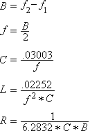
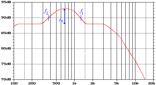
In the following formulas, the -3db points are the frequencies where the response is 3db less than the peak response in the middle of the notch.

f1 = First -3db point in Hz
f2 = Second -3db point in Hz
At = Attenuation in Db

